How to detect when a DFX RUGGEDrive memory token (SD card functionality) is inserted?
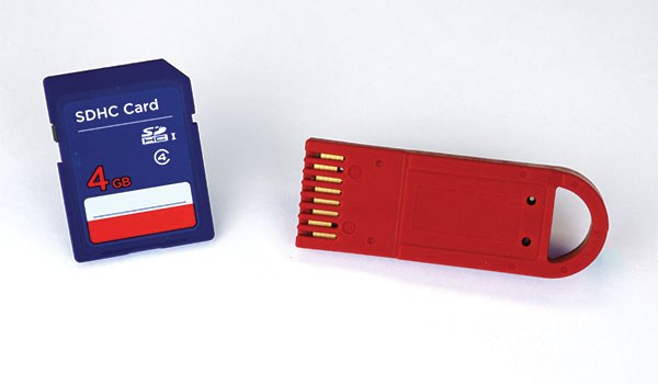
The first thing to consider is that a DFX memory token (red token to the right of the SD card in the image to the right) provides SD card functionality, but comes in the more robust RUGGEDrive™ form factor. It is literally an SD card in a non-SD card package. So, to answer the question of how to detect a DFX RUGGEDrive token, you can look to the answer of, “How does one detect when an SD card has been inserted?
There are two primary ways for a controller to detect the presence of an SD card:
- The most straightforward method to detect the presence of an SD card is to use an SD card socket/receptacle that employs a mechanical switch. When a card is inserted, the Card Detection pin is commonly connected to ground. When the card is removed the connection to ground is broken.
- For SD card sockets/receptacles without a mechanical switch for card detection, there is an alternative method for card detection. The SD card pin labeled “CD/DAT3” (the CD stands for Card Detection) contains a 50 KΩ pull up resistor that is enabled on power up. For card detection, the host looks for this line to be pulled high. The SD Physical Layer Simplified Specification has a limited discussion on this method. The full specification has additional information, but is only available to SD card members.
DFX RUGGEDrive memory tokens use Datakey SlimLine receptacles. These receptacles do not have a mechanical switch to detect when a memory token is inserted. Instead, most Datakey memory tokens have a special contact called LOFO (which stands for Last On First Off) that is used for token detection. The LOFO contact in the memory token is internally tied to ground. RUGGEDrive tokens, however, do not have a LOFO contact, so engineers integrating a DFX memory token into an embedded design can utilize the CD/DAT3 pin as described above. Alternatively, we have designed a mechanical detection method that can be used with board-mount SlimLine receptacles.
To implement the mechanical detection method into a PCB design, follow these steps:
1. In the PCB design, locate a 0.035” diameter plated through-hole under the Pin 3 contact of the board-mount SlimLine receptacle. The through-hole should be located 0.532” away from the center of the Pin 3 through-hole contact of the SlimLine receptacle (assuming a through-hole version of the receptacle is used). See diagram below.
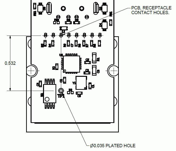
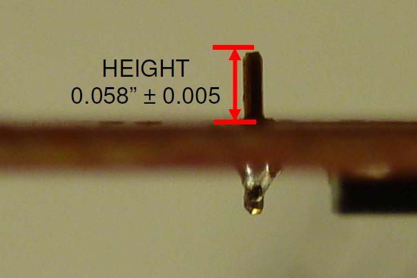
2. ATEK offers a stake (contact us for part number and pricing) that can be used for this application. Place the stake into the hole (labeled as TP1 in the figure above). The stake should be soldered in place so the height of the stake above the surface of the PCB (on the receptacle side of the board) is 0.058”. See image below. A fixture may be helpful in ensuring the stake is at the right height when soldered in place.
3. Pin 3 of the receptacle is connected to ground. When a DFX memory token is inserted into the receptacle, the Pin 3 contact will be depressed downward, making contact with the stake. The controller can monitor this line, which would typically be pulled high. When a token is inserted, the ground contact of the receptacle will make contact with the stake, pulling it low. The video below shows a memory token being inserted into an SlimLine receptacle, depressing the receptacle contacts to the point where the Pin 3 contact makes contact with the stake.
If you have questions or would like more information on how to detect when a DFX RUGGEDrive memory token is inserted or removed, please contact us.